

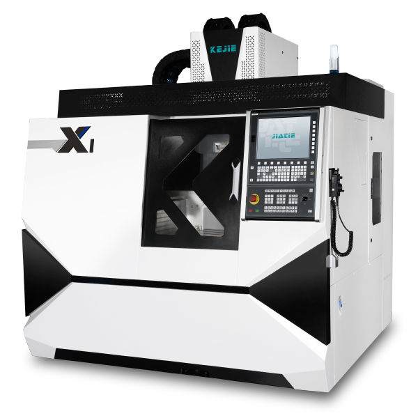
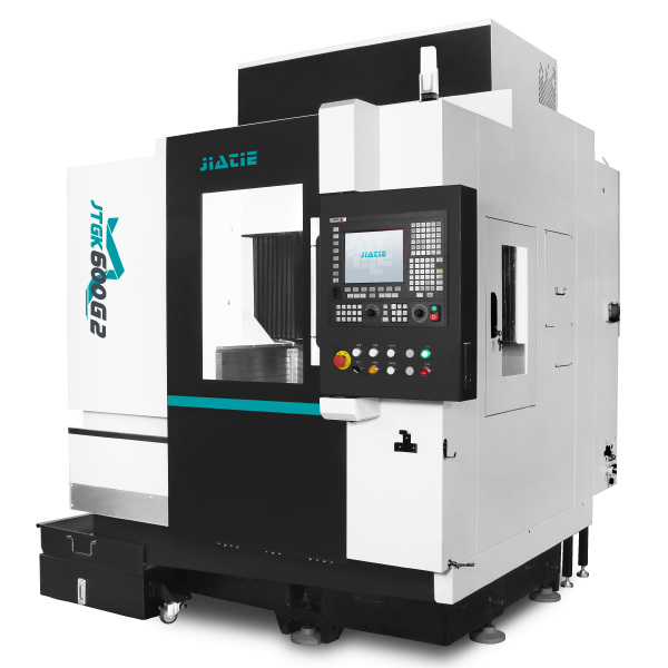
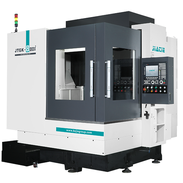
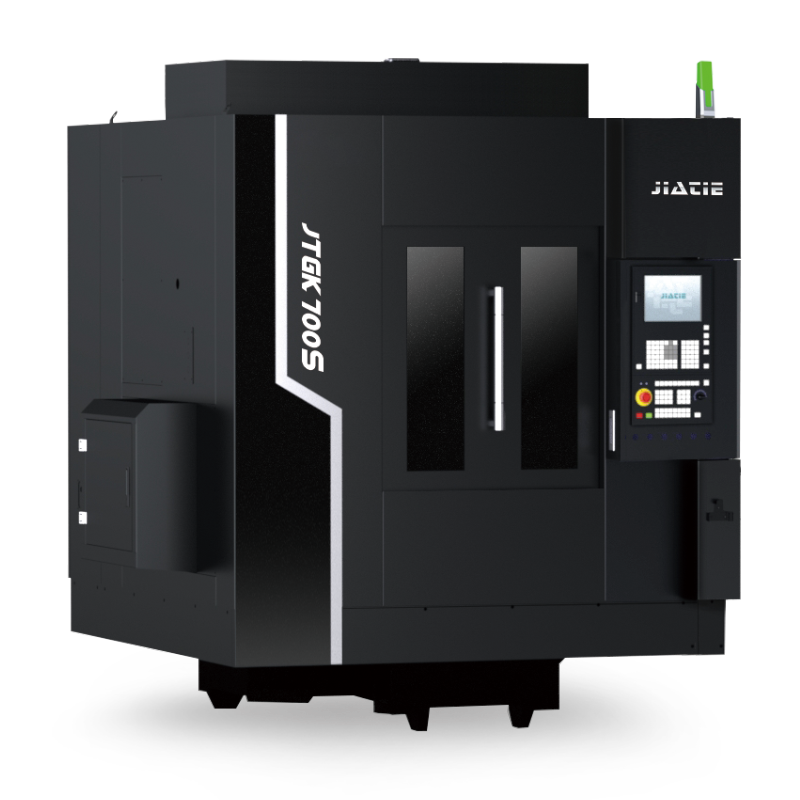
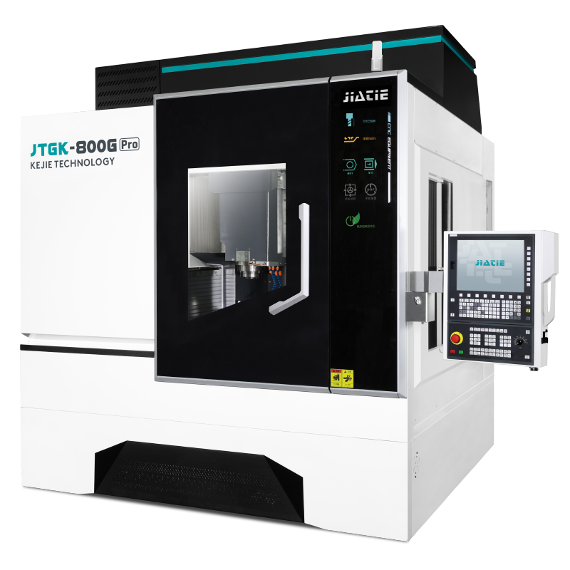
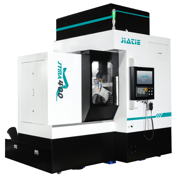
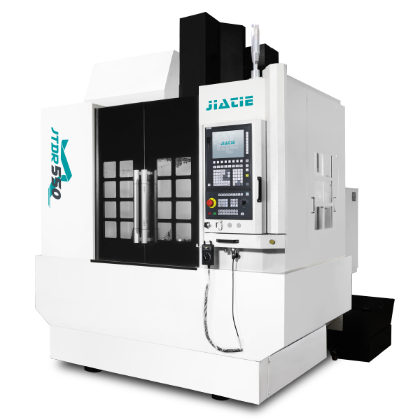
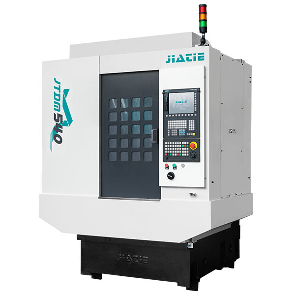
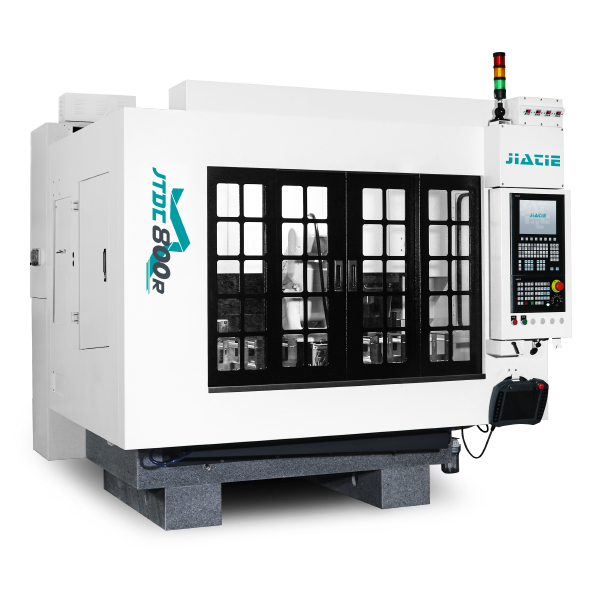
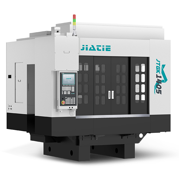
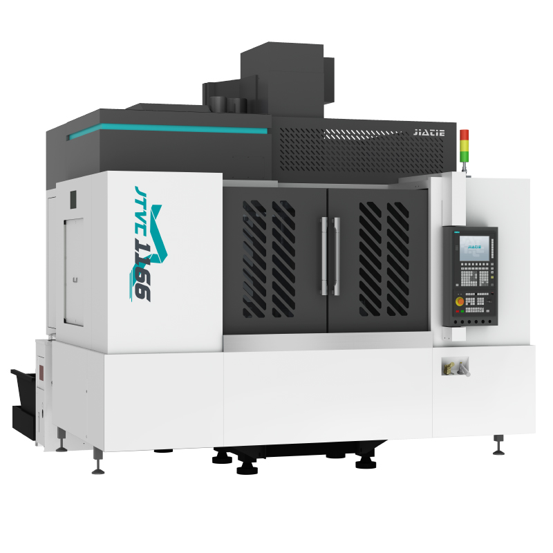
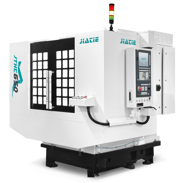
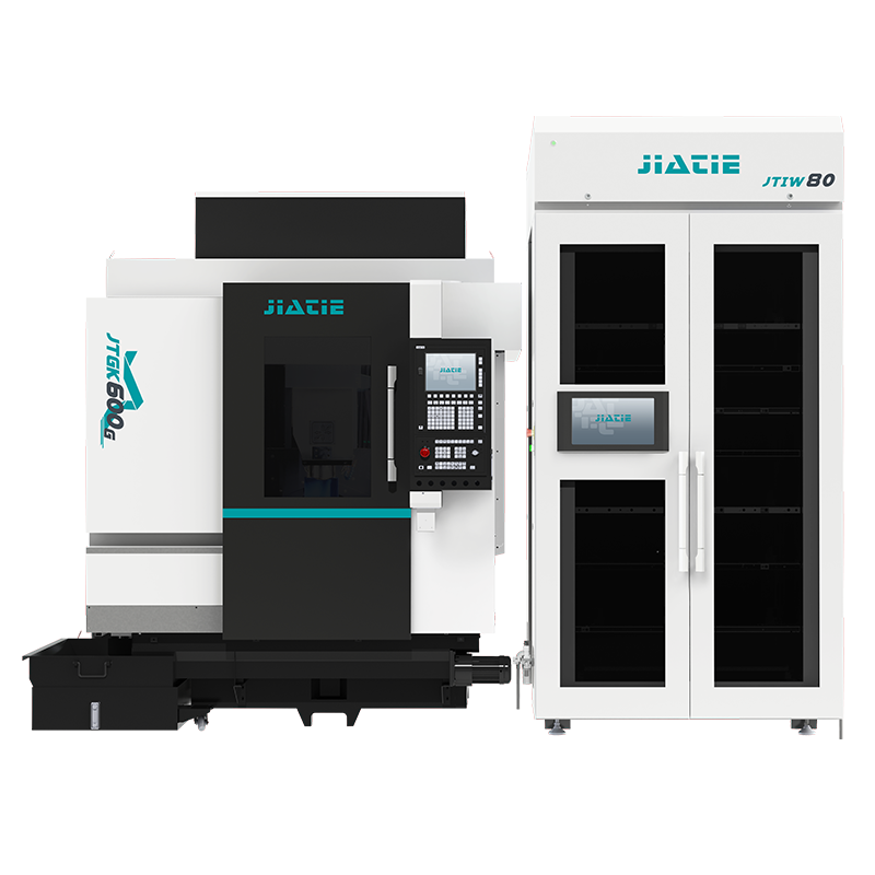
Ultra-Precision Graphite Machining is a manufacturing process that removes microscopic amounts of graphite material with extremely high accuracy to produce complex, high-tolerance components. The process combines high-speed CNC technology, rigid machine structures, precision cutting tools, and advanced control systems to achieve dimensional tolerances as tight as ±0.002–0.005 mm and excellent surface finishes.
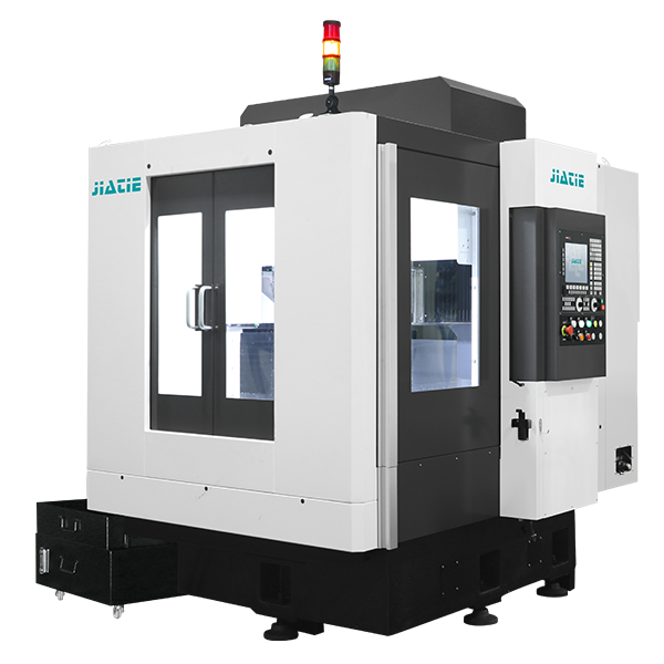
1. Basic Working Principle
The principle of ultra-precision Graphite Machining is based on controlled material removal. Instead of removing large amounts of material at once, the machine removes very thin layers of graphite using specialized cutting tools under precisely controlled conditions.
The machining system continuously coordinates:
High-speed spindle rotation
Multi-axis CNC motion
Precision tool positioning
Constant feed control
Dust extraction
Temperature compensation
These elements work together to minimize vibration, reduce tool wear, and maintain exceptional machining accuracy.
2. Machining Process Flow
Step 1: CAD Design
Engineers create a 3D CAD model of the graphite component, including:
Dimensions
Surface requirements
Tolerances
Electrode geometry
Complex cavities
Step 2: CAM Programming
CAM software generates optimized toolpaths based on:
Material properties
Cutting depth
Tool diameter
Feed rate
Spindle speed
Toolpaths are optimized to reduce machining marks while maintaining precision.
Step 3: Workpiece Fixing
The graphite block is securely clamped on the machine table.
Stable workholding is critical because even slight movement can affect micron-level accuracy.
Step 4: High-Speed CNC Machining
The CNC controller synchronizes multiple axes while the spindle rotates at high speed.
Typical machining operations include:
Face milling
Pocket milling
Contour milling
Slot machining
Deep cavity machining
3D surface machining
The cutting tool removes graphite layer by layer with minimal cutting force.
Step 5: Continuous Dust Extraction
Unlike metal machining, graphite generates extremely fine conductive dust.
A high-efficiency vacuum system continuously removes dust to:
Protect machine components
Improve machining accuracy
Prevent contamination
Extend tool life
Step 6: Precision Inspection
After machining, the component is measured using:
Coordinate Measuring Machine (CMM)
Optical measuring systems
Laser scanners
Surface roughness testers
Any deviation is corrected through compensation machining if necessary.
3. Core Working Mechanism
High-Speed Spindle
The spindle rotates cutting tools at very high speeds, typically:
20,000–60,000 RPM
Some precision machines exceed 80,000 RPM
Higher spindle speeds reduce cutting forces and produce smoother surfaces.
Micro Cutting
Ultra-precision machining removes only microscopic amounts of graphite per cutting pass.
Typical cutting parameters include:
Cutting depth: 0.01–0.20 mm
Small feed per tooth
Constant chip load
This minimizes chipping and edge damage.
Multi-Axis Motion Control
Modern Graphite Machining Centers often feature:
3-axis machining
4-axis machining
5-axis simultaneous machining
Multi-axis control enables machining of complex geometries in a single setup, reducing positioning errors.
Thermal Stability
Temperature changes can affect machining accuracy.
Ultra-precision machines employ:
Constant-temperature workshops
Thermal compensation software
Symmetrical machine structures
Low-expansion materials
These measures maintain consistent dimensional accuracy.
4. Why Graphite Is Suitable for Ultra-Precision Machining
Graphite possesses unique material characteristics:
| Property | Effect on Machining |
|---|---|
| Low hardness | Easy to cut |
| Excellent machinability | Supports high-speed machining |
| Low cutting force | Reduces tool deflection |
| No burr formation | Produces clean edges |
| High temperature resistance | Ideal for EDM electrodes |
| Dimensional stability | Maintains machining accuracy |
5. Key Technologies Behind Ultra-Precision Graphite Machining
Modern systems integrate several advanced technologies:
High-speed CNC control
Linear motor drives
Precision ball screws
Hydrostatic or air-bearing spindles
Automatic tool changers
Tool length measurement
Automatic tool wear compensation
Intelligent dust collection
Real-time motion correction
Together, these technologies ensure stable, repeatable machining performance.
6. Factors Affecting Machining Accuracy
Several factors influence the final machining quality:
Graphite material grade
Grain size
Tool material
Tool wear
Spindle rigidity
Machine vibration
Feed rate
Cutting speed
Environmental temperature
Dust removal efficiency
Optimizing these factors helps achieve superior dimensional accuracy and surface quality.
7. Typical Applications
Ultra-precision graphite machining is widely used for manufacturing:
EDM graphite electrodes
Semiconductor components
Precision molds
Glass molding dies
Aerospace parts
Medical device components
Precision fixtures
Optical mold inserts
Electronic packaging molds
Conclusion
The working principle of ultra-precision graphite machining is the precise, computer-controlled removal of microscopic layers of graphite using high-speed cutting tools and advanced CNC systems. By integrating high-speed spindles, multi-axis motion control, thermal stability, and efficient dust extraction, manufacturers can produce highly accurate graphite components with exceptional surface quality, making the process indispensable for industries such as mold manufacturing, aerospace, semiconductor production, and precision engineering.